AN204
Product: PicStic 1-4
Using the Interrupts Available to the PicStic 1, 2, 3, and 4
Date: 8/22/00
Introduction: This application note demonstrates how to use the interrupts on the PicStic.
Background: The definition of interrupt is a signal to the microprocessor that stops the execution of a running program in order to execute a program of higher priority. The PicStic has four interrupts available. It has an overflow interrupt for Timer 0, an EEPROM write complete interrupt, a hardware interrupt on PB0, and an input change on PB7, PB6, PB5, and PB4 interrupt. The INTCON register is located at 0BH and it is defined as follows:
bit 7: GIE: Global Interrupt Enable bit
1 = Enables all un-masked interrupts
0 = Disables all interrupts
bit 6: EEIE: EE Write Complete Interrupt Enable bit
1 = Enables the EE write complete interrupt
0 = Disables the EE write interrupt
bit 5: T0IE: TMR0 Overflow Interrupt Enable bit
1 = Enables the TMR0 interrupts
0 = Disables the TMR0 interrupts
bit 4: INTE: PB0/INT Interrupt Enable bit
1 = Enables the PB0/INT interrupt
0 = Disables the PB0/INT interrupt
bit 3: RBIE: PB Port Change Interrupt Enable bit
1 = Enables the PB port change interrupt
0 = Disables the PB port change interrupt
bit 2: T0IF: TMR0 Overflow Interrupt Flag bit
1 = TMR0 has overflowed (must be cleared by software)
0 = TMR0 did not overflow
bit 1: INTF: PB0/INT Interrupt Flag bit
1 = The PB0/INT interrupt occurred
0 = The PB0/INT interrupt did not occur
bit 0: RBIF: PB Port Change Interrupt Flag bit
1 = When at least one of the PB4-PB7 pins change state (must be cleared in software)
0 = None of the PB4-PB7 pins have changed state
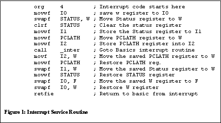
How it works: In order for an interrupt to work properly an Interrupt Service Routine (ISR) must be written in memory location 04H of the PicStic. The ISR listed in figure 1, should be inserted in the PBH.INC file for the PicBasic Compiler after the command JMP startclr. The JMP startclr is already provided in the PBH.INC file as a comment, just un-comment it.

This Interrupt Service Routine saves and restores all of the necessary registers to return from an interrupt. The ISR also calls a basic routine with a line label inter:, so your interrupt routine can be written in PicBasic rather than assembly language.
The following is a schematic to show how to connect the PicStic for using the PB0 interrupt along with it's associated Program Listing.

The program listed below will keep printing Micromint, Inc until PB2 is pressed. When PB2 is pressed the PicStic sets the interrupt flag and jumps to the ISR.
Program Listing:
' This program demonstrates using the PB0 interrupt. The interrupt service
' routine must be placed in the PBH.INC file before this program is compiled..
Poke $0B,$90 'Enable the Global Interrupt Bit
'also enable the PB0 Interrupt
Begin: SEROUT 7,N9600,("Micromint, Inc.",13,10)
PAUSE 500
GOTO Begin
inter: SEROUT 7,N9600,("Interrupt OCCURED",13,10) ' Print if an interrupt has occured
Poke $0B,$90 'Clear the PB0 interrupt
RETURN