POLAROID 6500 SERIES SONAR RANGING MODULE PID #615077
Features:
Description
The 6500 Series is an economical sonar ranging module that can drive all Polaroid electrostatic transducers with not additional interface. This module, with a simple interface, is able to measure distances from 6 inches to 35 feet. The typical absolute accuracy is ± 1% of the reading over the entire range.
This module has an external blanking input that allows selective echo exclusion for operation on a multiple-echo mode. The module is able to differentiate echos from objects that are only three inches apart. The digitally controlled-gain, variable-bandwidth amplifier minimizes noise and side-lobe detection in sonar applications.
The module has an accurate ceramic-resonator-controlled 420-kilohertz time-base generator. An output based on the 420-kilohertz time base is provided for external use. The sonar transmit output is 16 cycles at a frequency of 49.4 kilohertz.
The 6500 Series module operates over a supply voltage range from 4.5 volts to 6.8 volts and is characterized for operation from 0° C to 40° C.
Absolute Maximum Ratings
Voltage from any pin to ground (see Note
1) . . . . . . . . . . . . . . . . . . . . . . . . . . . . . . . . . . . . .
. . . 7 V
Voltage from any pin except XDCR to VCC (see Note 1). . . . . . . . . . . .
. . . . . . . . . . . . . 7 to 0.5 V
Operating free-air temperature range. . . . . . . . . . . . . . . . . . . .
. . . . . . . . . . . . . . . . . . .0° C to 40° C
Storage temperature range . . . . . . . . . . . . . . . . . . . . . . . . .
. . . . . . . . . . . . . . . . . . . .-40° C to 85° C
NOTE 1: The XCDR pin may be driven from 1 volt to 400 volts typical with respect to ground.
Recomended Operating Conditions
| Minimum | Maximum | Unit | ||
| Supply voltage, VCC | 4.5 | 6.8 | V | |
| High-level input voltage,VIH | BLINK,BINH, INIT | 2.1 | V | |
| Low-level input voltage,VIL | BLINK,BINH, INIT | 0.6 | V | |
| Echo and OSC output voltage | 6.8 | V | ||
| Delay time, power up to INIT high | 5 | ms | ||
| Recycle period | 80 | ms | ||
| Operating free-air temperature, TA | 0 | 40 | °C | |
Electrical Characteristics Over Recommended Ranges
of Supply Voltage and Operating Free-Air Temperature (unless otherwise noted)
|
PARAMETER |
TEST CONDITIONS | MIN | TYP | MAX | UNIT | |
| Input Current | BLINK,BINH, INIT | VI = 2.1 V | 1 | mA | ||
| High-level input voltage,VOH | ECHO, OSC | VOH = 5.5 V | 100 | µA | ||
| Low-level input voltage,VOL | ECHO, OSC | IOL = 1.6 mA | 0.4 | V | ||
| Transducer bias voltage | TA = 25°C | 200 | V | |||
| Transducer output voltage (peak-to-peak) | TA = 25°C | 400 | V | |||
| Number of cycles for XDCR output to reach 400 V | C=500 pF | 7 | ||||
| Internal blanking interval | 2.38* | ms | ||||
| Frequency during 16-pulse transmit period | OSC output | 49.4* | kHz | |||
| XMIT output | 49.4* | |||||
| Frequency after 16-pulse transmit period | OSC output | 93.3* | kHz | |||
| XMIT output | 0 | |||||
| Supply current, ICC | During Transmit Period | 2000 | kHz | |||
| After Transmit Period | 100 | |||||
* These typical values apply for a 420-kHz ceramic resonator
Operating With Polaroid Electrostatic Transducer
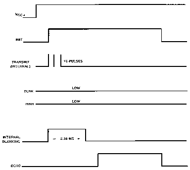
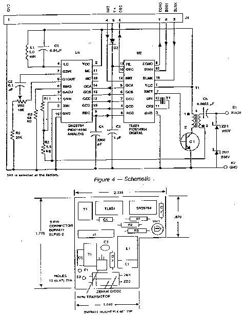
There are two basic modes of operation for the 6500 Series Sonar ranging module: single-echo mode and multiple-echo mode. The application of power (VCC), the activation of the Initiate (INIT) input, and the resulting transmit output, and the use of the Blanking Inhibit (BINH) input are basically the same for either mode of operation. After applying power (VCC) a minimum of 5 milliseconds must elapse before the INIT input can be taken high. During this time, all internal circuitry is reset and the internal oscillator stabilizes. When INIT is taken high, drive to the Transducer XDCR output occurs. Sixteen pulses at 49.4 kilohertz with 400-volt amplitude will excite the transducer as transmission occurs. At the end of the 16 transmit pulses, a dc bias of 200 volts will remain on the transducer as recommended for optimum operation.
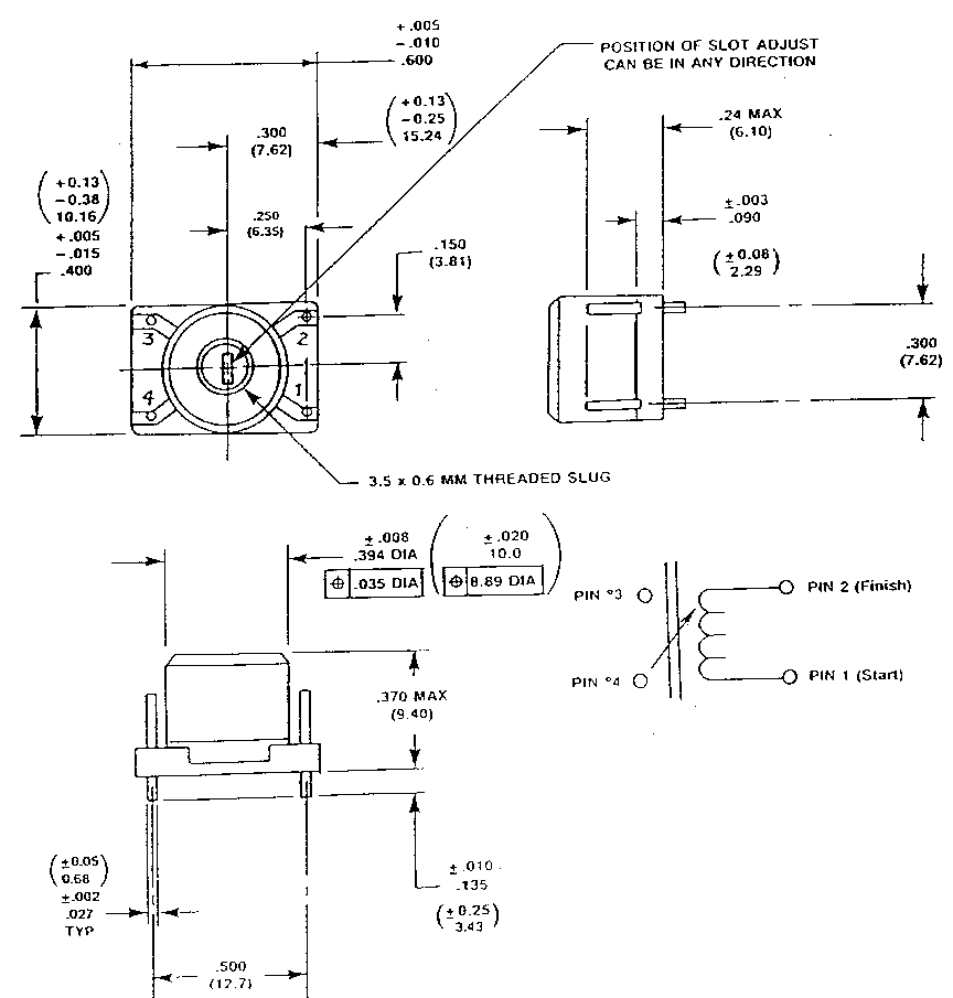
| Electrical & Physical Specification | |
| 1 | Nominal Inductance: 1.04 mH |
| 2 | Minimum Adjustment Range: .96 - 1.13mh MIN |
| 3 | Test Frequency: 50 KHZ |
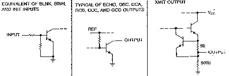
INPUT/OUTPUT SCHEMATICS
In order to eliminate ringing of the transducer from being detected as a return signal, the Receive (REC) input of the ranging control IC is inhibited by internal blanking for 2.38 milliseconds after the initiate signal. If a reduced blanking time is desired, then the BINH input can be taken high to end the blanking of the Receive input anytime prior to internal blanking. This may be desirable to detect objects closer than 1.33 feet corresponding to 2.38 milliseconds and may be done if transducer damping is sufficient so that ringing is not detected as a return signal.
In the single-echo mode of operation (Figure 1), all that must be done next is to wait for the return of the transmitted signal, traveling at approximately 0.9 milliseconds per foot out and back. The returning signal is amplified and appears as a high-logic-level echo output. The time between INIT going high and the Echo (ECHO) output going high is proportional to the distance of the target from the transducer. If desired, the cycle can now be repeated by returning INIT to a low-logic level and then taking it high when the next transmission is desired.
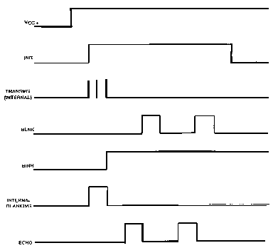
If there is more than one target and multiple echos will be detected from a single transmission, then the cycle is slightly different (Figure 2). After receiving the first return signal which causes the ECHO output to go high, the Blanking (BLNK) input must be taken high then back low to reset the ECHO output for the next return signal. The blanking signal must be at least 0.44 milliseconds in duration to account for all 16 returning pulses from the first target and allow for internal delay times. This corresponds to the two targets being 3 inches apart.
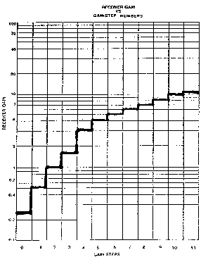
During a cycle starting with INIT going high, the receiver amplifier gain is incremented higher at discrete times (Figure 3) since the transmitted signal is attenuated with distance. At approximately 38 milliseconds, the maximum gain is attained. For this reason, sufficient gain may not be available for objects greater than 35 feet away. Although gain may be increased by varying R1 (Figure 4), there is a limit to which the gain can be increased for reliable module operation. This will vary from application to application. The modules are "kitted" prior to their final test during manufacture. This is necessary because the desired gain distribution is much narrower than the module gain distribution if all were kitted with one value resistor. As kitted, these modules will perform satisfactorily in most applications. As a rule of thumb, the gain can be increased up to a factor of 4, if required, by increasing R1 correspondingly. Gain is directly proportional to R1.
Potentiometer VR1 (Figure 4) provides an interstage gain adjustment for the module. It can be used to trim the overall range of gain set by fix resistor R1.
C· I· A· R· C· I· AS C· I· R· C· U· I· T C· E· L· L· A· R
***** CAUTION *****
OSC. AND ECHO OUTPUTS
MAY REQUIRE PULL-UPS.
3.9K IS ACCEPTABLE
AN ULTRASONIC
RANGING SYSTEM
by Steve Ciarcia
Build the SonarTape
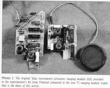
Those of you who have followed the Circuit Cellar projects over the years will recognize that I have discussed sonar and ultrasonic ranging before. November 1980s "Home In on the Range! An Ultrasonic Ranging System" used the Polaroid Ultrasonic Ranging System Designers Kit. This $150 kit, based on a modified, custom-manufactured sonar-ranging circuit board from Texas Instruments for Polaroids SX-70 camera, greatly simplified the circuitry normally associated with ultrasonics. The November 1980 project described circuit additions that facilitated connection of the ranging kit to a computers I/O (input/output) port.
To my knowledge, these kits are still available from Polaroid if you are interested in producing the stepper-motor-driven scanning system described in the original article. However, if you are looking for a cost-effective distance sensor for your computer, youll be happy to know that LSI (large-scale integration) technology did not stand still in the interim. Texas Instruments introduced a new sonar-ranging module that is both cost-effective and simple to integrate into computer-based systems.
Ill first describe this new module in detail and then demonstrate how easily you can attach it to a computer or use it independently with an LCD (liquid-crystal display) to create an electronic tape measure.
The Sonar-Ranging Module
The latest Texas Instruments sonar-ranging module, the SN28827, is actually an updated and higher-functioning version of the original SX-70 module, both of which are shown in photo 1. The newer unit has similar performance characteristics but requires far less support circuitry and interfacing hardware. It is designed to drive a 50-kHz 300-volt (V) electrostatic transducer, which Polaroid is still manufacturing. The module and the transducer are the only components necessary to measure distances from 1.33 to 35 feet with an accuracy of ± 2 percent.
In operation, a pulse is transmitted toward a target and the resulting echo detected. The elapsed time between the transmission and echo detection is a function of the distance to the target. Basically, this distance in feet is simply the elapsed time in seconds (actually milliseconds) multiplied by the speed of sound in feet per second (approximately 1100 ft/sec). More specifically, the rate is 1.78 milliseconds (ms) per round-trip foot. It takes 3.55 ms for a pulse to leave the transducer, strike a target 2 feet away and return to the transducer.
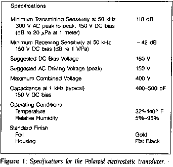
The transducer most frequently used with this module is the instrument-grade Polaroid electrostatic transducer (see figure 1 for its specifications), which acts as a speaker in the transmit mode and a microphone in the receive mode. The transducer (shown in photo 2 and disassembled into its component parts in figure 2) is 1.5 inches in diameter and consists of a 3-millimeter gold-plated foil stretched over a concentrically grooved aluminum disc.
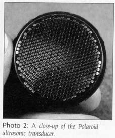
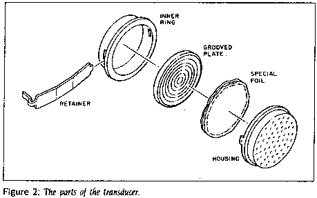
The foil, electrically insulated yet bonded closely to the metallic backplate, forms a capacitor. The foil is the moving element in the transducer that converts electrical energy into sound and the returning echo into electrical energy.
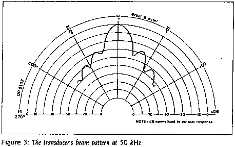
The Polaroid sensor is larger and, in my opinion, considerably more expensive than other 50-kHz transducers. However, it is designed this way for a specific purpose. (Ive tried 50-kHz transducers from two other manufacturers with no success). The diameter of the transducer determines its directional sensitivity. The Polaroid unit is extremely directional, as indicated in the graph of acoustical-signal strength shown in figure 3.
OPERATING THE MODULE
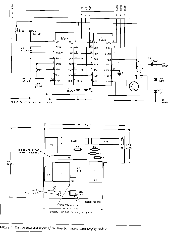
The sonar-ranging module (pictured in photo 3 and diagramed in figure 4) is a two-chip, 2 by 2-inch module. It is a 12-component, custom-manufactured module built around the Texas Instruments TL851 and TL852 sonar-ranging controller/receiver chip set. In small quantities, the assembled module is far less expensive than the individual components, and it eliminates the ever-present aggravation of finding the correct coils and chokes. Electrical connection is made through an eight-conductor flat ribbon cable or direct solder attachment to the connector base, which contains three output lines, three input lines, power and ground.
The two basic modes of operation for the module are single echo and multiple echo. The single-echo mode implies that only one target exists and that a single ranging value is desired. In the multiple-echo mode, the echo monitoring time is extended to "hear" the echo from objects farther away than the closest target. Differentiating among these echoes can be a data-reduction nightmare, so I will limit my discussion and the use of the ranging module to the single-echo mode.
Figure 5 is the basic timing diagram of the ranging module. Within 5 ms of applying power (at 4.5 V to 6.8 V), the internal circuitry has reset and stabilized and the module is ready. The distance-measuring sequence is activated by raising the INIT input line to a logic 1 state. This enables the 420 kHz on-board ceramic resonator, and 16 cycles of a 300-V 49.4 kHz (420 kHz divided by 8.5) signal are generated. The 16 cycles are passed through a driver/transformer combination that boosts the signals magnitude to 300 V at the transducer. At the end of the 16 cycles, a DC bias of 150 V remains on the transducer for optimum operation, and the oscillator output steps up to 93 kHz (420 kHz divided by 4.5), where it remains as long as INIT is high.
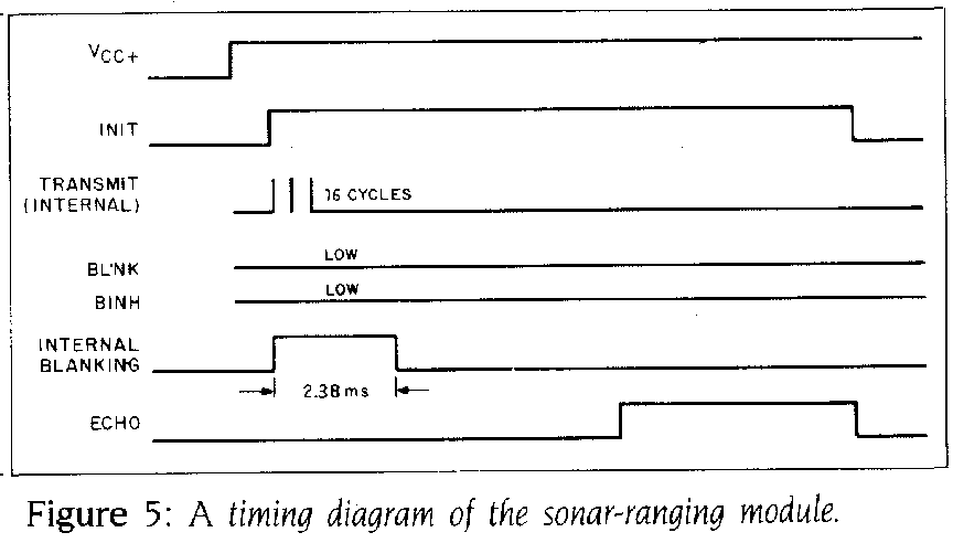
In order to prevent any ringing in the transducer from being detected as a return signal, the receive input of the ranging control IC (integrated circuit) is inhibited by an internal blanking signal for 2.38 ms. This blanking interval corresponds to 1.33 feet, which is the minimum distance that the ranging module can sense without external control intervention. To detect objects closer than 1.33 feet, the blanking inhibit line, BINH, can be taken high prior to 2.38 ms to enable the receiver.
In the single-echo mode, all that must be done is to wait for the echo from the target. After INIT, the transmitted pulse travels at a rate of 0.9 ms per foot. When the ranging module hears the echo, the ECHO output line goes high. The difference in time between INIT and ECHO both going high is a measure of the distance to the target. This elapsed time can be measured through a timing loop in a computer or gated with the oscillator output to increment a counter and drive a display. I will explore both of these techniques.
One final note on the ranging-module electronics. If you have experimented with ultrasonics, youve probably found, as I have, that fixed-distance reception is far easier to accomplish than variable-distance reception. Sound intensity decreases geometrically proportional to increases in distance. If you have designed a transmitter-and-receiver system that works well at 6 feet, it may not function at 12 feet without substantially increasing the receiver sensitivity (gain) to account for the reduced echo amplitude. Leaving the sensitivity at a high level and reducing the distance again invites other interference and false-echo-detection problems. To adequately compensate for changing distances, the sensitivity setting must also be adjustable with distance.
The TI ranging module dynamically tailors the receive amplifiers sensitivity. Lowe amplification is needed for close objects, higher amplification for distant echoes. Twelve gain steps within the range of 0 to 35 feet are automatically incremented as the time between INIT and ECHO lengthens. If the distance is 6 feet, the receiver will be at its second gain setting. At 20 feet it will be at its sixth level. The twelfth level is sufficient for unaided reception of echoes from 35 feet. The addition of a direction cone to the transducer, which will further improve sensitivity, will facilitate measuring distances beyond 35 feet.
Computer Connection
Figure 6 is the schematic for connecting the ranging module to the parallel port of a computer. The entire single-echo-mode interface requires only 1 input bit and 1 output bit. The output bit connects to the INIT line; the input bit connects to the ECHO line. To measure distance, the computer merely raises the INIT line and measures the time until ECHO goes high. The repetition rate depends on the distance. The cycle is repeated when INIT is lowered and raised again. This can occur at any point after ECHO. For short distances, a 100-Hz repetition rate is possible. To allow a full 35-foot range, however, the repetition rate should be limited to 10 Hz.
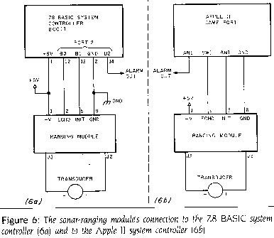
Unlike the Polaroid Designers Kit, which is specified to run n 6 V, the TI ranging module can function between 4.5 and 6.8 V. If you use a 5-V supply, the ranging module I/O is TTL (transistor-transistor logic) compatible and can be connected directly to most computers. The module normally requires about 100 milliamperes (mA) except during the 16-cycle transmission period, when it can reach 2 amperes (A). Any power source intended for use with the module should have an intermittent power rating this high. For portable operation, you can use either standard AA or larger alkaline batteries or Polaroids Polapulse high-current batteries.
For the purposes of this article, I chose to demonstrate connection of the ranging module to an Apple II and the Z8 system-controller board, which is an improved descendant of the original Z8-based computer controller presented in the June and July 1980 Circuit Cellar articles. The description of connecting the ranging module to the Z8 system controller through a parallel I/O port, measuring the elapsed time in a callable machine-language routine, and manipulating the results within the tine BASIC interpreter are transferable in principle to any computer. (I have since had a Z8 FORTH chip produced that is interchangeable with the Z8671 tiny BASIC chip. The FORTH chip could also have been used.) By using the Z8 board, however, I can produce a dedicated measuring system that can sense and average a number of readings, make decisions, activate specific control outputs, and communicate readings to larger host systems serially.
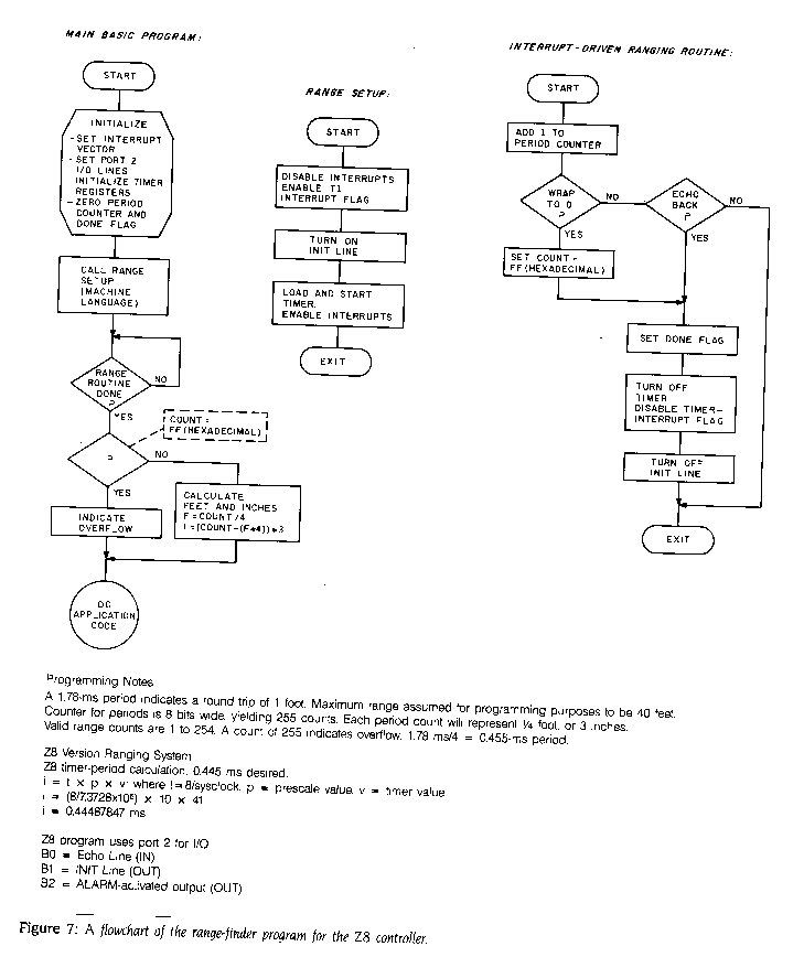
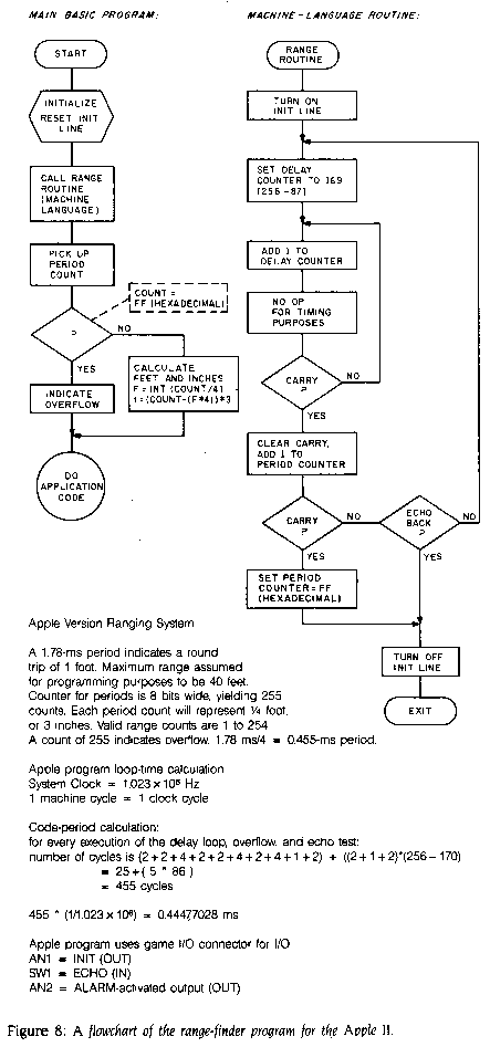
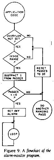
Figure 7 is a block diagram of the necessary steps to initialize the module and measure distance with the Z8. Figure 8 is a block diagram of the Apple II version of the same code. Figure 9 is the block diagram of a typical proximity-detector application with alarm outputs. Listings 1,2, and 3 show the code to perform these tasks.
Electronic Tape Measure
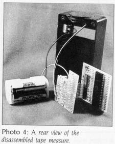
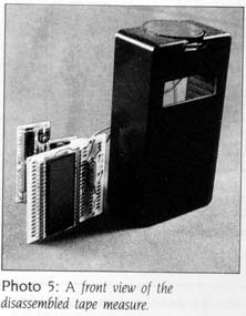
While describing the electrical characteristics and computer connection of the ranging module might ordinarily suffice as a Circuit Cellar project. I was intrigued by the simplicity of using the ranging module and decided to build the electronic tape measure shown in photos 4 and 5. The circuit shown in figure 10 required only three additional CMOS (complementary metal-oxide semiconductor) chips and can be constructed as a hand-held device.
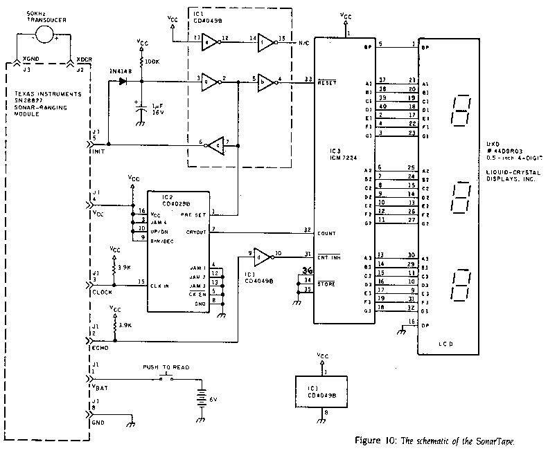
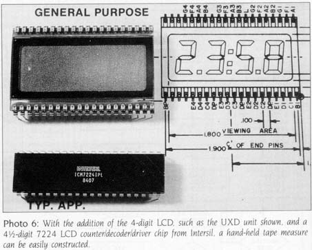
The Circuit Cellar Sonar Tape Measure, hereafter called SonarTape, consists of the TI ranging module, a CD4049 inverter, a CD4029 counter, and an Intersil ICM7224 4½-digit LCD counter/decoder/driver chip (shown in photo 6). When pointed at an object or a wall and activated, the SonarTape transmits once and holds its reading (so that you can turn the unit and see the display if it wasnt already in view). The LCD indicates the distance in feet and tenths of feet.
The SonarTape is activated by turning on the power (6 V provided by four AA alkaline cells) to the circuit through a momentary push button. A resistor/capacitor timing circuit connected to Vcc and attached to pin 3 of IC1 resets IC3, present IC2 and keeps the INIT input line to the ranging module low until the 5 ms power-on stabilization time has passed. When the capacitor charges up to a logic 1 level, the INIT line goes to a logic 1, allowing the ranging module to transmit.
Once the INIT line goes high, the clock output, CLOCK, from the ranging module is enabled, and a 93.333-kHz clock (after the first 16 cycles at 49.4 kHz) is presented to the clock input of IC2. Configured as a divide-by-16 counter, the carry output, pin 7, will be at 5.83333 kHz. This frequency is connected to the count input of the counter/decoder/driver chip, IC3, which continues to count input pulses (started when INIT went high) until the ECHO line, connected through an inverter to the count-inhibit line on IC3 goes high, indicating reception of the echo. Clock pulses will therefore have been counted during the elapsed time period between INIT and ECHO.
If the elapsed time were 6 ms, about 34 clock cycles would have been counted by IC3. With the decimal point permanently set between the least and next most significant digit, the indication on the LCD would have been 3.4 feet. Similarly, 31 ms of elapsed time would allow about 175 cycles to occur, which would indicate 17.5 feet.
IN CONCLUSION
I did think about commercial applications for SonarTape. Just because Id like one, however, doesnt mean it has any potential. The high cost of the additional circuitry, packaging, and LCD make it either a high-priced novelty or cost-effective only in mass production. Ill stick with my prototype and wait for the next development iteration so that I can cover this subject in another four years.
One additional application that I started prototyping but discontinued as not completely germane to this article was a blind sonar sensor. Such a device (for the blind or any sightless application, such as firemen entering a smoke-filled room) would conceivably allow a sightless person to "hear" a picture of the environment by sweeping a hand-held ranging unit in front as he or she walked. Rather than a visual display, the distance measurement would be a tone whose frequency was a function of distance. My initla design consisted of continuously triggering the INIT line with a 5-Hz oscillator and applying the INIT and ECHO signals to an AND gate to produce a single pulse output whose pulse width was the elapsed time between INIT and ECHO. Next, using an integrator circuit, or even a simple RC (resistor-capacitor) combination, the pulse width is converted to a DC voltage level. The longer the pulse width, the higher the DC level.
When ECHO goes high, the integrator output would be sampled and held (until the next ranging sample) with a sample-and-hold circuit. The output of the sample-and-hold circuit is connected to a voltage-controlled oscillator such as the XR4151 or XR2206. Short distances produce low tones: long distances result in high tones. A little bit of experience recognizing tone patters should allow any of us to walk, without seeing.
I chose not to pursue the design at this time. If any of you build a working unit, however, Id like to know about it. Among the hundreds of letters I receive each month are some from readers who might benefit by the information.
Finally, Im not ending this article by discussing all the possible applications for the TI ranging module. The number is so great that they are impossible to list. Now that you know the unit exists and how to attach it to a computer, perhaps youll demonstrate some novel uses. For me, its on to the next project.
The following is available from
The Micromint Inc.
902 Waterway Place
Longwood, FL 32750
(407)262-0069
for orders only 800 635-3355
One Texas Instruments SN28827 sonar-ranging module and one Polaroid electrostatic transducer. Data sheets are included.
Editors Note: Steve often refers to previous Circuit Cellar articles. Most of these past articles are available in reprint books from BYTE Books, McGraw-Hill Book Company, POB 400, Hightstown, NJ 08250.
Ciarcias Circuit Cellar, Volume I covers articles that appeared in BYTE from September 1977 through November 1978. Volume II covers December 1978 through June 1980. Volume III covers July 1980 through December 1981. Volume IV covers January 1982 through June 1983.